Product & Services

data center guys

Product and Services

Kingsmich is proud to accept responsibility for the functionality of your IT Infrastructure. We provide all the service and support you need to keep your business running productively. Kingsmich is proud to offer 24/7 onsite, phone and email support. Call us today

    • Virus Removal
    • Computer/Laptop Repair
    • Network Installation
    • Server Installation/Monitoring
    • Data Backup Onsite/Offsite
    • Blackberry Server installation
    • Computer/Laptop Optimization


  • Computer Forensics
  • Consulting
  • 24/7 Onsite, Phone and Email
Tagged with: ,
Posted in Uncategorized

CCNA NOTE

CCNA NOTE


The CCNA covers the subject below which candidate must know before the exam, Let go over them briefly.


Go get your Certification


OSI Reference Model and Cisco Three Layer Model
osi-model

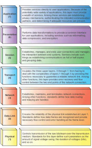
Each OSI layer contain a set of functions performed by programs to enable data to travel from a source to a destination on a network.

In this article I will provide brief descriptions of each layer in the OSI reference model.

Application Layer

The application layer is the OSI layer that is closest to the user. This layer provides network services to the user’s applications. It differs from the other layers in that it does not provide services to any other OSI layer, but only to applications outside the OSI reference model. Applications layer provide a platform to access the data of remote computer.

The application layer protocols that you should know are as follows:

  • SNMP (Simple Network Management Protocol) — Communicates status and allows control of networked devices.
  • TFTP (Trivial File Transfer Protocol) — Simple, lightweight file transfer.
  • DNS (Domain Naming System) — Translates a website name (easy for people) to an IP address (easy for computers).
  • DHCP (Dynamic Host Configuration Protocol) — Assigns IP, mask, and DNS server (plus a bunch of other stuff) to hosts.
  • Telnet— Provides a remote terminal connection to manage devices to which you are not close enough to use a console cable.
  • HTTP (Hypertext Transfer Protocol) — Browses web pages.
  • FTP (File Transfer Protocol) — Reliably sends/retrieves all file types.
  • SMTP (Simple Mail Transfer Protocol) — Sends email.
  • POP3 (Post Office Protocol v.3) — Retrieves email.
  • NTP (Network Time Protocol) — Synchronizes networked device clocks.

Presentation layer

The presentation layer is responsible for formatting data so that application-layer protocols (and then the users) can recognize and work with it. Presentation layer format the file extensions—such as .doc, .jpg, .txt, .avi, and so on. you realize that each of these file types is formatted for use by a particular type of application. The presentation layer taking the application layer data and marking it with the formatting codes so that it can be viewed reliably when accessed later. If necessary, the presentation layer might be able to translate between multiple data formats by using a common format.

The Session Layer

The session layer establishes, manages, and terminates sessions between two communicating hosts. It provides its services to the presentation layer. The session layer also synchronizes dialogue between the presentation layers of the two hosts and manages their data exchange. For example, web servers have many users, so many communication processes are open at a given time. Therefore, keeping track of which user communicates on which path is important.

Transport Layer

The transport layer is possibly the most important layer for exam study purposes. A lot is going on here, and it is heavily tested.

The transport layer’s main jobs

  • It sets up and maintains a session connection between two devices.
  • It can provide for the reliable or unreliable delivery of data across this connection.
  • It multiplexes connections, allowing multiple applications to simultaneously send and receive data. When
  • Implementing a reliable connection, sequence numbers and acknowledgments (ACKs) are used.
  • Flow control (through the use of windowing or acknowledgements)
  • Reliable connections (through the use of sequence numbers and Acknowledgement )

Transport layer use two protocols for sending data TCP and UDP.

TCP
TCP is connection oriented protocols. Connection-oriented transmission is said to be reliable. Thinks TCP as registry AD facility available in Indian post office. For this level of service, you have to buy extra ticket and put a bunch of extra labels on it to track where it is going and where it has been. But, you get a receipt when it is delivered, you are guaranteed delivery, and you can keep track of whether your shipment got to its destination. All of this costs you more—but it is reliable!

UDP
UDP is connection less protocols. Connection-less transmission is said to be unreliable. Now, don’t get too wrapped up in the term “unreliable” this doesn’t mean that the data isn’t going to get there; it only means that it isn’t guaranteed to get there. Think of your options when you are sending a postcard, put it in the mailbox, and chances are good that it will get where it’s supposed to go—but there is no guarantee, and stuff does go missing once in a while. On the other hand, it’s cheap.

The transport layer can use two basic flow control methods:

  • Ready/not ready signals
  • Windowing

There are two problems with the use of ready/not ready signals to implement flow control.
First, the destination may respond to the source with a not ready signal when its buffer fills up. While this message is on its way to the source, the source is still sending information to the destination, which the destination will probably have to drop because its buffer space is full.
The second problem with the use of these signals is that once the destination is ready to receive more information, it must first send a ready signal to the source, which must receive it before more information can be sent. In many implementations, the window size is dynamically negotiated up front and can be renegotiated during the lifetime of the connection.

In windowing a window size is defined between two host engaged in data transmission. And sender host will wait for an acknowledgement signal after sending the segments equal to window size. If any packet lost in way receiver will respond with acknowledgement for lost packet. And sender will send lost packet again.

Reliability

When reliability is necessary, it should cover these four items:

  • recognizing lost packets and having them re-sent
  • recognizing packets that arrive out of order and reordering them
  • detecting duplicate packets and dropping the extra ones
  • Avoiding congestion

Connection Multiplexing/Application Mapping

Transport layer assigns a unique set of numbers for each connection. These numbers are called port or socket numbers. TCP, and UDP, provide a multiplexing function for a device: This allows multiple applications to simultaneously send and receive data.
Imagine a server that performs a number of functions—for example email, web pages, FTP, and DNS. The server has a single IP address, but can perform all these different functions for all the hosts that want to connect to it. The transport layer (layer 4) uses port numbers to distinguish between different types of traffic that might be headed for the same IP address.

Port numbers are divided into ranges by the IANA. Following are the current port ranges:

Port number descriptions
0–1023 Well-Known—For   common TCP/IP functions and applications
1024–49151 Registered—For   applications built by companies
49152–65535 Dynamic/Private—For   dynamic connections or unregistered applications

Common TCP and UDP Port Numbers

TCP UDP
FTP 20, 21 DNS 53
Telnet 23 DHCP 67,68
SMTP 25 TFTP 69
DNS 53 NTP 123
HTTP 80 SNMP 161
POP 110
NNTP 119
HTTPS 443

Network Layer

The network layer provides a logical topology and layer-3 addresses. Routers function at the network layer. This layer is responsible for three main functions:

  • Defines logical addresses used at layer-3
  • Finds paths, based on the network numbers of logical addresses, to reach destination devices
  • Connects different data link types together, such as Ethernet, FDDI, Serial, and Token Ring

IP packet
Where the transport layer uses segments to transfer information between machines, the Internet layer uses datagram’s. Datagram is just another word for packet.

The IP protocol is mainly responsible for these functions:

  • Connectionless data delivery: best effort delivery with no data recovery capabilities
  • Hierarchical logical addressing to provide for highly scalable internetworks

IP addresses are broken into two components:

  • Network component Defines on what segment, in the network, a device is located
  • Host component defines the specific device on a particular network segment

Two types of packets are used at the Network layer: data and route updates.

Data packets
Used to transport user data through the internetwork. Protocols used to support data traffic are called routed protocols; examples of routed protocols are IP and IPv6.

Route update packets
Used to update neighboring routers about the networks connected to all routers within the internetwork. Protocols that send route update packets are called routing protocols; examples of some common ones are RIP, RIPv2, EIGRP, and OSPF. Route update packets are used to help build and maintain routing tables on each router.

IP Classes

  • Class A addresses range from 1-126: 00000001-01111111.
  • Class B addresses range from 128-191: 10000000-10111111.
  • Class C addresses range from 192-223: 11000000-11011111.
  • Class D addresses range from 224-239: 11100000-11101111.
  • Class E addresses range from 240-254:
  1. 0 is reserved and represents all IP addresses;
  2. 127 is a reserved address and is used for testing, like a loop back on an interface:
  3. 255 is a reserved address and is used for broadcasting purposes.

Public addresses are Class A, B, and C addresses that can be used to access devices in other public networks, such as the Internet. Public IP address assign authority The Internet Assigned Numbers Authority (IANA) is ultimately responsible for handing out and managing public addresses. Normally you get public addresses directly from your ISP, which, in turn, requests them from one of five upstream address registries:

  • American Registry for Internet Numbers (ARIN)
  • Reseaux IP Europeans Network Coordination Center (RIPE NCC)
  • Asia Pacific Registry for Internet Numbers (APNIC)
  • Latin American and Caribbean Internet Address Registry (LACNIC)
  • African Network Information Centre (AfriNIC)

Private IP and ISP

Private ip address can be used to configure private network. You can use private ip to build your network without paying a single rupees. But one biggest problem with private ip is that with private you can not access the internet. This is the point where ISP comes from. ISP purchase a bulk of public ip address and provide them on rent. Whatever you pay to ISP for accessing internet is actually the charge of using public ip address.

Private ip address:- Not route able in public network

  • Class A: 10.0.0.0-10.255.255.255 (1 Class A network)
  • Class B: 172.16.0.0-172.31.255.255 (16 Class B networks)
  • Class C: 192.168.0.0-192.168.255.255 (256 Class C networks)
Protocol Description
IP IP of TCP/IP,   featuring routable 32-bit addressing.
IPX The equivalent of IP   in Novell Netware.
ICMP Internet Connection   Management Protocol. Incorporates Ping and Traceroute, which are layer 3   link-testing utilities.
OSPF, IGRP, EIGRP, RIP, ISIS Dynamic routing   protocols that learn about remote networks and the best paths to them from   other routers running the same protocol.
ARP, RARP Address Resolution   Protocol (and Reverse ARP). ARP learns what MAC address is associated with a   given IP address. Reverse ARP learns an IP address given a MAC address.

Data link layer

Main functions of data link layer is

  • Defining the Media Access Control (MAC) or hardware addresses
  • Defining the physical or hardware topology for connections
  • Defining how the network layer protocol is encapsulated in the data link layer frame
  • Providing both connectionless and connection-oriented services
  • Defines hardware (MAC) addresses as well as the communication process that occurs within a media.
  • The first six hexadecimal digits of a MAC address form the OUI.
  • MAC addresses only need to be unique in a broadcast domain,
  • You can have the same MAC address in different broadcast domains (virtual LANs).

There are two specifications of Ethernet frame Ethernet II and 802

802.2 use a SAP or SNAP field to differentiate between encapsulatedlayer-3 payloads.

With a SNAP frame, the SAP fields are set to 0xAA and the type field is used to indicate the layer-3 protocol. One of the issues of the original SAP field in the 802.2 SAP frame is that even though it is eight bits (one byte) in length, only the first six bits are used for identifying upper-layer protocols, which allows up to 64 protocols.

802.2 SNAP frame support of up to 65,536 protocols

Ethernet II’s Version of Ethernet

  • Ethernet II does not have any sub layers, while IEEE 802.2/3 has two: LLC and MAC.
  • Ethernet II has a type field instead of a length field (used in 802.3). IEEE 802.2 defines the type for IEEE Ethernet

Physical Layer

The Physical layer communicates directly with the various types of actual communication media. Different kinds of media represent these bit values in different ways. Some use audio tones, while others utilize state transitions—changes in voltage from high to low and low to high. Specific protocols are needed for each type of media to explain the proper bit patterns to be used, how data is encoded into media signals, and the various qualities of the physical media’s attachment interface.

Fiber Cabling

Two types of fiber are used for connections: multimode and single-mode.

Multimode fiber
has a fiber thickness of either 850 or 1300 nanometers (nm), and the light signal is typically provided by an LED. When transmitting a signal, the light source is bounced off of the inner cladding (shielding) surrounding the fiber. Multimode fiber can achieve speeds in the hundreds of Mbps range, and many signals can be generated per fiber.

Single-mode fiber
has a fiber thickness of 1300 or 1550 nm and uses a laser as the light source. Because lasers provide a higher output than LEDs, single-mode fiber can span over 10 kilometers and have speeds up to 100Gbps. With single-mode fiber, only one signal is used per fiber.

  • Loss factor is used to describe any signal loss in the fiber before the light source gets to the end of the fiber.
  • Connector loss is a loss that occurs when a connector joins two pieces of fibers: a slight signal loss is expected.
  • Attenuation describe the signal loose due to distance
  • Microbending is when a wrinkle in the fiber, typically where the cable is slightly bent, causes a distortion in the light source.
  • Macrobending is when there is leakage of the light source from the fiber, typically from a bend in the fiber cable. to overcome this problem over long distances, optical amplifiers can be used.

Two main standards are used to describe the transmission of signals across a fiber:

SONET is defined by the Exchange Carriers Standards Association (ECSA) and American National Standards Institute (ANSI) and is typically used in North America.

SDH is an international standard used throughout most of the world (with the exception of North America). Both of these standards define the physical layer framing used to transmit light sources, which also includes overhead for the transmission.

Cisco’s three-layer hierarchical model


  1. Core Layer

The core provides a high-speed layer-2 switching infrastructure and typically does not manipulate packet contents.

  1. Distribution Layer

The distribution layer provides a boundary between the access and core layers. It contains routers and switches. Routers are used to provide the logical boundary–broadcasts are contained within the access layer and Filtering policies can be implemented to restrict traffic flows.

  1. Access Layer
  2. The access layer provides the user’s initial access to the network, which is typically via switches or hubs.

TCP/IP protocol

The TCP/IP protocol stack has four layers. Note that although some of the layers in the TCP/IP protocol stack have the same names as layers in the OSI reference model, the layers have different functions in each model, as is described in the following list:

Application layer:

The application layer handles high-level protocols, including issues of representation, encoding, and dialog control. The TCP/IP model combines all application-related issues into one layer and ensures that this data is properly packaged for the next layer.

Transport layer:

The transport layer deals with QoS issues of reliability, flow control, and error correction. One of its protocols, TCP, provides for reliable network communications.

Internet layer:

The purpose of the Internet layer is to send source datagrams from any network on the internetwork and have them arrive at the destination, regardless of the path they took to get there.

Network access layer:

The name of this layer is broad and somewhat confusing. It is also called the host-to-network layer. It includes the LAN and WAN protocols and all the details in the OSI physical and data link layers.

Subnetting Supernetting and VLSM

This section would introduce subnetting. You will be able to subnet a network in your head after going through this section. In addition, you will learn about Variable Length Subnet Masks (VLSMs) and how to design a network using VLSMs. This would finish with summarization techniques and configurations.

Cisco devices administration and configuration

This section introduces you to Cisco equipment. In this section you will learn how to connect to it and make initial configurations, as well as how to connect it to other devices to build a network. You will review the different types of network connections available, with particular emphasis on those that are tested in the CCNA exams. You will also look at where a Cisco device stores the various files it needs to operate, the files needed for the boot process, and the backup and restoration of system files

For our purposes, we use a Catalyst 2960 or 3560 switch and a 1600, 1700, or 2600 series router as example devices. Most of the commands you learn in this section also apply to more advanced models.

Cisco devices are very costly. For exam preparation you could use simulators. Several simulators are available choose one that best suites you. We would packet tracer for configuration.

Switching VLAN STP VTP DTP Ether Channels

In this section we would cover following CCNA objectives

Use the CLI to discover neighbors on a network

Manage switch startup and configuration

Manage Cisco IOS images, configuration files, and devices on the network

Describe how and when to implement and verify VLANs and trunking, and then implement them on the network

Describe situations in which a spanning tree is used, and implement it on the network

Describe the application and configuration of inter-VLAN routing for a medium-sized routed network

Describe situations in which security is required at Layer 2, and implement it on the network

Identify an approach for troubleshooting and isolating common switched network problems, and offer solutions


WAN protocols HDLC PPP Frame Really NAT PAT

This section introduces the components of a VPN solution for WAN connectivity, explains how to configure a PPP connection, and describes Frame Relay operation, configuration, and troubleshooting.


In this section we would cover following CCNA objectives

Describe the uses of VPNs for site-to-site and remote-user access

Connect to a service provider over a network and describe the operation and configuration of PPP

Connect to a service provider over a network and describe the operation and the basic configuration of Frame Relay

Identify an approach for troubleshooting common Frame Relay problems and offer solutions


IPv6 features concepts and configurations

The most important drawbacks to IP version 4 (IPv4) is the limited number of unique network addresses; the Internet is running out of address space.

Two solutions to this dilemma are Network Address Translation (NAT) and IP version 6 (IPv6).

NAT provides a short-term solution to this problem by translating private IPv4 addresses into globally unique, routable IPv4 addresses.

IPv6 is the long-term solution. By increasing the size of an IP address to 128 bits, IPv6 increases the total number of addresses that are available. This section discusses both solutions.

No matter for which certification are you preparing IPv6 has become the essential part of all major certifications. In order to get IT certification you must be familiar with IPv6. With a complete series of article on ipv6 tutorials we have tried our level best to give you whatever universal certifications require from IT professionals.

Limitations of IPv4

Builtin Features of IPv6

Differences between IPv4 and IPv6

IPv6 Terms and Concepts

IPv6 address format

Special IPv6 Addresses

How to configure IPv6 Address

IPv6 Address Auto configuration Process

How to assign IPv6 address in Server 2008

IPv6 Enabled command line tools

IPv6 ICMP

IPv6 Neighbor Discovery Protocol

IPv6 Transition Method and Strategies

How to configure Cisco Router with IPv6

How to configure routing with IPv6 step by step guides

Routing Static Dynamics RIP OSPF IGRP EIGRP

In this section we would cover following CCNA objectives

Describe the purpose and types of dynamic routing protocols

Describe the operation and implementation of distance vector routing protocols

Describe the operation and implementation of link-state routing protocols

Basic of routing distance vector protocol problems solutions

How to configure router step by step guide

How to configure Cisco router in CCNA step by step guide

Static Route configuration on Router

How to configure Static Route on router

RIP Routing information protocol

How to configure RIP routing information protocol

Enhanced Interior Gateway Routing Protocol Configurations

How to configure enhanced interior gateway routing protocol

OSPF Open Shortest Path First Routing protocol

How to configure open shortest path first routing protocol

How to configure EIGRP with RIP on same network


Wireless networking on Cisco Router


In this section we will introduces Wireless LAN (WLAN) technology. We will discuss the standards associated with WLANs, how WLANs are deployed and the basics of how they operate, security threats specific to WLANs and measures to mitigate them, and the essential steps to connect and configure an access point (AP) and a client.

Basic of Wireless Networking

Wireless networking Access Modes and security Factors

Wireless Networking Security and MAC Address Filtering

Types of Wireless Networks

How to Configure Wireless Network Step by Step guides


. Network Security access lists standards and extended

For this reason, Cisco expects you to have a general understanding of network security.

In section we would cover following topics

Describing the increase in security threats and the need for a security policy

Explaining general methods to mitigate threats

Describing the functions of common security appliances/applications

Describing the recommended practices of securing network device

Network Definitions Characteristics Components locations

Network Security Types of attacks

Network Security Mitigating Common Threats

Access Control List Standard and Extended

Network security Reconnaissance attack

How to configure standard access list on router

How to configure extended access list on router


Go get your Certification

The CCNA program was created to provide a solid introduction to the Cisco Internetwork Operating System (IOS) and Cisco hardware. Cisco certification programs can help networking professionals succeed as they pursue their careers.

Company Cisco System
Exam Number 640-802
Associated   Certifications CCNA
Duration 90 minutes (45-55   questions)
Available Languages English, Japanese,   Chinese, Spanish, Russian, Korean, French, Portuguese
Authorize Exam   Organizer Pearson VUE
Prerequisites None ( Basic   Networking Knowledge recommended)
Substitute Exam 640-822 ICND1-   Interconnecting Cisco Networking Devices Part 1
640-816 ICND2-Interconnecting Cisco Networking Devices Part 2
Validity period Three years
Recertification To recertify, pass   the ICND2 exam, or pass the current CCNA exam, or pass a CCNA Concentration   exam (wireless, security, voice), or pass the current CCDA exam, or pass any   642 – XXX professional level or Cisco Specialist exam (excluding Sales   Specialist exams), or pass a current CCIE or CCDE written exam.


Posted in Uncategorized

Configuring EIGRP Part 2, Practical.

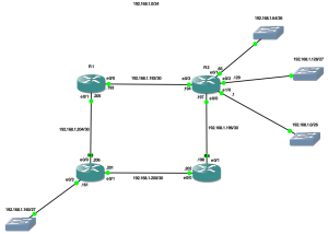
VLSM Lab - GNS3 Layout

I have subnetted the 192.168.1.0 network using VLSM to cater or networks of the following sizes:

192.168.1.0 – 60 Hosts
192.168.1.64 – 40 Hosts
192.168.1.128 – 30 Hosts
192.168.1.160 – 25 Hosts

First I configure EIGRP on R1 on just one interface (linked to R2).

R1

R1#conf t
Enter configuration commands, one per line. End with CNTL/Z.
R1(config)#router eigrp 10
R1(config-router)#network 192.168.1.193 0.0.0.0
R1(config-router)#no auto-summary
R1(config-router)#end

I have used 10 as the AS for EIGRP, this must be the same for all the routers. I have turned off auto-summary so I can have better control of summarisation. I use some show commands to check its running on just the specified interface.

R1#sh ip eigrp interfaces
IP-EIGRP interfaces for process 10

Xmit Queue Mean Pacing Time Multicast Pending
Interface Peers Un/Reliable SRTT Un/Reliable Flow Timer Routes
Et0/0 0 0/0 0 0/1 0 0

I can also see that there are currently no neighbors.

R1#sh ip eigrp neighbors
IP-EIGRP neighbors for process 10

I now enable EIGRP on R2 and I see the adjacency form.

R2

R2#conf t
Enter configuration commands, one per line. End with CNTL/Z.
R2(config)#router eigrp 10
R2(config-router)#network 192.168.1.194 0.0.0.0
R2(config-router)#network 192.168.1.197 0.0.0.0
R2(config-router)#
*Mar 1 00:42:40.399: %DUAL-5-NBRCHANGE: IP-EIGRP(0) 10: Neighbor 192.168.1.193 (Ethernet0/3) is up: new adjacency

Back on R1 i check the neighbor table.

R1

R1#sh ip eigrp neighbors
IP-EIGRP neighbors for process 10
H Address Interface Hold Uptime SRTT RTO Q Seq
(sec) (ms) Cnt Num
0 192.168.1.194 Et0/0 12 00:00:39 13 200 0 3

Checking the route table on R1 i can also see the EIGRP route.

R1#sh ip route
Codes: C – connected, S – static, R – RIP, M – mobile, B – BGP
D – EIGRP, EX – EIGRP external, O – OSPF, IA – OSPF inter area
N1 – OSPF NSSA external type 1, N2 – OSPF NSSA external type 2
E1 – OSPF external type 1, E2 – OSPF external type 2
i – IS-IS, su – IS-IS summary, L1 – IS-IS level-1, L2 – IS-IS level-2
ia – IS-IS inter area, * – candidate default, U – per-user static route
o – ODR, P – periodic downloaded static route

Gateway of last resort is not set

192.168.1.0/30 is subnetted, 3 subnets
C 192.168.1.204 is directly connected, Ethernet0/1
C 192.168.1.192 is directly connected, Ethernet0/0
D 192.168.1.196 [90/307200] via 192.168.1.194, 00:04:36, Ethernet0/0

On R4 I enable EIGRP.

R4

R4#conf t
Enter configuration commands, one per line. End with CNTL/Z.
R4(config)#router eigrp 10
R4(config-router)#network 192.168.1.198 0.0.0.0
R4(config-router)#network 192.168.1.202 0.0.0.0

And on R3 I enable EIGRP.

R3#conf t
Enter configuration commands, one per line. End with CNTL/Z.
R3(config)#router eigrp 10
R3(config-router)#network 192.168.1.201 0.0.0.0
R3(config-router)#network 192.168.1.206 0.0.0.0
R3(config-router)#network 192.168.1.161 0.0.0.0

From R3 I check the routing table and I can see routes to the all the other networks I have configured so far.

R3#sh ip route
Codes: C – connected, S – static, R – RIP, M – mobile, B – BGP
D – EIGRP, EX – EIGRP external, O – OSPF, IA – OSPF inter area
N1 – OSPF NSSA external type 1, N2 – OSPF NSSA external type 2
E1 – OSPF external type 1, E2 – OSPF external type 2
i – IS-IS, su – IS-IS summary, L1 – IS-IS level-1, L2 – IS-IS level-2
ia – IS-IS inter area, * – candidate default, U – per-user static route
o – ODR, P – periodic downloaded static route

Gateway of last resort is not set

192.168.1.0/24 is variably subnetted, 5 subnets, 2 masks
C 192.168.1.200/30 is directly connected, Ethernet0/1
C 192.168.1.204/30 is directly connected, Ethernet0/0
D 192.168.1.192/30 [90/332800] via 192.168.1.202, 00:00:09, Ethernet0/1
D 192.168.1.196/30 [90/307200] via 192.168.1.202, 00:00:09, Ethernet0/1
C 192.168.1.160/27 is directly connected, Ethernet0/2

What is missing from my routing table is routes for all the networks hanging off R2. This is because I used the wildcard mask of 0.0.0.0 to specify that EIGRP only ran on certain interfaces. To enable EIGRP for all networks on R2 I will add a new network with no wildcard mask. This is similar to commands used when setting up RIP.

R2

R2#conf t
Enter configuration commands, one per line. End with CNTL/Z.
R2(config)#router eigrp 10
R2(config-router)#network 192.168.1.0

Now when I check the routing table on R3 i can see all the new networks attached to R2.

R3

R3#sh ip route
Codes: C – connected, S – static, R – RIP, M – mobile, B – BGP
D – EIGRP, EX – EIGRP external, O – OSPF, IA – OSPF inter area
N1 – OSPF NSSA external type 1, N2 – OSPF NSSA external type 2
E1 – OSPF external type 1, E2 – OSPF external type 2
i – IS-IS, su – IS-IS summary, L1 – IS-IS level-1, L2 – IS-IS level-2
ia – IS-IS inter area, * – candidate default, U – per-user static route
o – ODR, P – periodic downloaded static route

Gateway of last resort is not set

192.168.1.0/24 is variably subnetted, 8 subnets, 3 masks
D 192.168.1.64/26 [90/332800] via 192.168.1.202, 00:02:14, Ethernet0/1
D 192.168.1.0/26 [90/332800] via 192.168.1.202, 00:02:14, Ethernet0/1
C 192.168.1.200/30 is directly connected, Ethernet0/1
C 192.168.1.204/30 is directly connected, Ethernet0/0
D 192.168.1.192/30 [90/332800] via 192.168.1.202, 00:04:25, Ethernet0/1
D 192.168.1.196/30 [90/307200] via 192.168.1.202, 00:04:25, Ethernet0/1
C 192.168.1.160/27 is directly connected, Ethernet0/2
D 192.168.1.128/27 [90/332800] via 192.168.1.202, 00:02:14, Ethernet0/1

Now I can see all the networks.

I want to test my reliance between R3 and R2. To do this I will test connectivity and then shut down an interface on R4. Hopefully routing will continue.

R3

R3#ping r2

Type escape sequence to abort.
Sending 5, 100-byte ICMP Echos to 192.168.1.197, timeout is 2 seconds:
!!!!!
Success rate is 100 percent (5/5), round-trip min/avg/max = 4/9/16 ms

R3 can ping R2 successfully. Now I shutdown R4′s interface.

R4

R4(config)#int ethernet 0/0
R4(config-if)#shut

R3

R3#ping r2
Type escape sequence to abort.
Sending 5, 100-byte ICMP Echos to 192.168.1.197, timeout is 2 seconds:
..
*Mar 1 01:16:28.347: %DUAL-5-NBRCHANGE: IP-EIGRP(0) 10: Neighbor 192.168.1.202 (Ethernet0/1) is down: holding time expired…
Success rate is 0 percent (0/5)

Pings fail! I check R1 and find that it is only routing for network 192.168.1.192 (on interface 192.168.1.193).

R1

R1#sh ip protocols
Routing Protocol is “eigrp 10″
Outgoing update filter list for all interfaces is not set
Incoming update filter list for all interfaces is not set
Default networks flagged in outgoing updates
Default networks accepted from incoming updates
EIGRP metric weight K1=1, K2=0, K3=1, K4=0, K5=0
EIGRP maximum hopcount 100
EIGRP maximum metric variance 1
Redistributing: eigrp 10
EIGRP NSF-aware route hold timer is 240s
Automatic network summarization is not in effect
Maximum path: 4
Routing for Networks:
192.168.1.193/32
Routing Information Sources:
Gateway Distance Last Update
192.168.1.194 90 00:01:37
Distance: internal 90 external 170

I add the other interface into EIGRP for AS 10.

R1#conf t
Enter configuration commands, one per line. End with CNTL/Z.
R1(config)#router eigrp 10
R1(config-router)#network 192.168.1.205 0.0.0.0

Back on R3 I attempt to contact R2 again.

R3

R3#ping r2
Type escape sequence to abort.
Sending 5, 100-byte ICMP Echos to 192.168.1.197, timeout is 2 seconds:
!!!!!
Success rate is 100 percent (5/5), round-trip min/avg/max = 4/9/12 ms

And looking at my routing table I can see that the next hop to get to R2 is R1 whereas before it was R4

R3#sh ip route
Codes: C – connected, S – static, R – RIP, M – mobile, B – BGP
D – EIGRP, EX – EIGRP external, O – OSPF, IA – OSPF inter area
N1 – OSPF NSSA external type 1, N2 – OSPF NSSA external type 2
E1 – OSPF external type 1, E2 – OSPF external type 2
i – IS-IS, su – IS-IS summary, L1 – IS-IS level-1, L2 – IS-IS level-2
ia – IS-IS inter area, * – candidate default, U – per-user static route
o – ODR, P – periodic downloaded static route

Gateway of last resort is not set

192.168.1.0/24 is variably subnetted, 8 subnets, 3 masks
D 192.168.1.64/26 [90/332800] via 192.168.1.205, 00:01:22, Ethernet0/0
D 192.168.1.0/26 [90/332800] via 192.168.1.205, 00:01:22, Ethernet0/0
C 192.168.1.200/30 is directly connected, Ethernet0/1
C 192.168.1.204/30 is directly connected, Ethernet0/0
D 192.168.1.192/30 [90/307200] via 192.168.1.205, 00:01:22, Ethernet0/0
D 192.168.1.196/30 [90/332800] via 192.168.1.205, 00:01:22, Ethernet0/0
C 192.168.1.160/27 is directly connected, Ethernet0/2
D 192.168.1.128/27 [90/332800] via 192.168.1.205, 00:01:22,Ethernet0/0


* Good Credit to SynJunkie for excellent work of this cause.

Thanks kingsmich

Posted in Uncategorized

Step by step on how to configure router

Step by step on how you configure router

1.Choose a convenient location to begin installing your router such as an open floor space or table. This does not need to be the permanent location of the device. Particularly for wireless routers, you may find it necessary to re-position the unit after installing it as the cables / signals may not reach all areas needed. At the beginning, its better to choose a location where it’s easiest to work with the router and worry about final placement later.

2.Plug in the router’s electrical power source, then turn on the router by pushing the power button.

3.(Optional) Connect your Internet modem to the router. Most network modems connect via an Ethernet cable but USB connections are becoming increasingly common. The cable plugs into the router jack named “WAN” or “uplink” or “Internet.” After connecting the cable, be sure to power cycle (turn off and turn back on) the modem to ensure the router recognizes it.

4.Connect one computer to the router. Even if the router is a wireless model, connect this first computer to the router via a network cable. Using a cable during router installation ensures the maximum reliability of the equipment. Once a wireless router installation is complete, the computer can be changed over to a wireless connection if desired.

5.Open the router’s administration tool. From the computer connected to the router, first open your Web browser. Then enter the router’s address for network administration in the Web address field and hit return to reach the router’s home page.

Many routers are reached by either the Web address “http://192.168.1.1” or “http://192.168.0.1” Consult your router’s documentation to determine the exact address for your model. Note that you do not need a working Internet connection for this step.

6.Log in to the router. The router’s home page will ask you for a username and password. Both are provided in the router’s documentation. You should change the router’s password for security reasons, but do this after the installation is complete to avoid unnecessary complications during the basic setup.

7.If you want your router to connect to the Internet, you must enter Internet connection information into that section of the router’s configuration (exact location varies). If using DSL Internet, you may need to enter the PPPoE username and password. Likewise, if you have been issued a static IP address by your provider (you would need to have requested it), the static IP fields (including network mask and gateway) given to you by the provider must also must be set in the router.

8.If you were using a primary computer or an older network router to connect to the Internet, your provider may require you to update the MAC address of the router with the MAC address of the device you were using previously. Read How to Change a MAC Address for a detailed description of this process.

9.If this is a wireless router, change the network name (often called SSID). While the router comes to you with a network name set at the factory, you will never want to use this name on your network. Read How to Change the Router SSID for detailed instructions.

10.Verify the network connection is working between your one computer and the router. To do this, you must confirmed that the computer has received IP address information from the router. See How to Find IP Addresses for a description of this process.

11.(If applicable) Verify your one computer can connect to the Internet properly. Open your Web browser and visit a few Internet sites such as http://compnetworking.about.com/.

12.Connect additional computers to the router as needed. If connecting wirelessly, ensure the network name (SSID) of each is computer matches that of the router.

13.Finally, configure additional network security features as desired to guard your systems against Internet attackers. These WiFi Home Network Security Tips offer a good checklist to follow.

Tips: 1.When connecting devices with network cables, be sure each end of the cable connects tightly. Loose cables are one of the most common sources of network setup problems.

What You Need •A network router (wireless or wired) •Network adapters installed on all devices to be connected to the router •A working Internet modem (optional) •A Web browser installed at least one computer in the network

Posted in Uncategorized

RSA SECURITY ISSUE

Mobile Computing and Social NetworkingAggression and Social Norms EG351 w3 Analysis EG351 w3 assign 2 EG351 w3 assign1 EG351 w3-1 EG351 W10 asgn 2 EG351 wk 10 EG351_w1 assg 1 – Copy EG351_w1 assg 1 EG351_w1 assg 2doc – Copy EG351_w1 assg 2doc EG351_w1 assg 2doc EG351_w2 assg 2 EG351_w2 EG462 WK 9 – Copy EG462 WK 9 EG481 PROJ 3 WK9 – Copy EG481 PROJ 3 WK9 Project 2 wk 6 wk 9 assign 3eco 5500 week 2 DQs Estimating DemandAnalyze the APT Summit Findings article as well as the RSA Security Brief article and identify the vulnerabilities that existed in the system. An evolution in the goals and sophistication of computer network intrusions has rendered these approaches insufficient for the threats facing many modern networked organizations. A new class of adversaries, appropriately dubbed the “Advanced Persistent Threat” (APT), represents well-resourced and trained adversaries that conduct multi-year intrusion campaigns targeting highly sensitive and valuable data in an attempt to gain a competitive edge, particularly in international business and law, or nation-state political and military affairs. These adversaries accomplish their goals using advanced tools and techniques designed to circumvent most conventional computer network defense mechanisms and remain undetected in their intrusion efforts or presence on networks over long periods of time. 3.  Greg Rattray, Chief Executive Officer,Delta Risk LLC (SANS Institute, 2013).

According to Mike Cloppert Cyber Threat Intelligence Summit Co-Chairs, network defense techniques which leverage knowledge about these adversaries – known as cyber threat intelligence – can enable defenders to establish a state of information superiority which decreases the adversary’s likelihood of success with each subsequent intrusion attempt. Threat intelligence can be a force multiplier as organizations look to update their security programs and defenses to deal with increasingly sophisticated advanced persistent threats. Security managers need accurate, timely and detailed information to continuously monitor new and evolving attacks, and methods to exploit this information in furtherance of an improved defensive posture. Make no mistake about it: contemporaneous computer network defense contains a strong element of intelligence and counterintelligence that analysts and managers alike must understand and leverage. 5. The goal of this summit will be to equip attendees with knowledge on the tools, methodologies and processes they need to move forward with cyber threat intelligence. The SANS What Works in Cyber Threat Intelligence Summit will bring attendees who are eager to hear this information and learn about tools, techniques, and solutions that can help address these needs.

The tokens, of which 40 million have been deployed, and 250 million mobile software versions, are the market leader for two-factor authentication. They are used in addition to a password, providing a randomly generated number that allows a user to access a network. The tokens are commonly used in financial transactions and government agencies; one source who asked to remain anonymous said SecurID users in those sensitive areas were scrambling to figure out what to do in light of the breach.

Analyze the attack methods carried out in pursuit of the authentication breach and explain which methods were successful and why. The breach at RSA that could compromise the effectiveness of the firm’s two-factor authentication SecurID tokens was accomplished via phishing e-mails and an exploit for a previously unpatched Adobe Flash hole, RSA has revealed. According to, Elinor Mills The attacker sent two different phishing e-mails over a two-day period last month with a subject line of “2011 Recruitment Plan” to two small groups of employees who weren’t considered particularly high-profile or high-value targets, Uri Rivner, head of new technologies in consumer identity protection at RSA, wrote in a blog post. Attached to the e-mails was an Excel file that contained “The attacker in this case installed a customized remote administration tool known as Poison Ivy RAT (remote administration tool) variant,” Rivner wrote. “Often these remote administration tools, the purpose of which is simply to allow external control of the PC or server, are set up in a reverse-connect mode: this means they pull commands from the central command & control servers, then execute the commands, rather than getting commands remotely. This connectivity method makes them more difficult to detect, as the PC reaches out to the command and control rather than the other way around.” The type of attack RSA was hit with is known as an “Advanced Persistent Threat” (APT). Such attacks are often used to target source code and other information useful in espionage, and they involve knowledge of the company’s operations, network, and employees and their roles. With APTs, attackers often have months to snoop around the network and gather information. But RSA stopped this attack early on, although the attacker still had time to “identify and gain access to more strategic users,” Rivner said. “Since RSA detected this attack in progress, it is likely the attacker had to move very quickly to accomplish anything in this phase,” he added. Advanced Persistent Attacks often target source code and other information useful in espionage and involve knowledge of the company’s network, key employees, and workings. Attackers use social engineering and exploits hidden in e-mail and other messages to sneak key loggers and other snooping tools onto employees’ computers. Google announced last year that it and other companies had been targeted in such an attack and it later came out that attackers used an unpatched hole in Internet Explorer to get into the company computers. Google said at the time that intellectual property was stolen and that the attacks appeared to originate in China

According to CNET, RSA has sent security advisory notes to 60,000 customers, briefed 15,000 customers, and had one-on-one briefings with hundreds of customers in sensitive industries who have signed non-disclosure agreements to talk more specifically about how they can best protect themselves.

Suggest three (3) techniques or methods to protect against APT attacks in the future as the CSO for a large organization. simple defense strategies will go a long way to preparing businesses for APTs and reducing the risk, according to IT security professionals. Although some APTs, like Stuxnet, target zero-day vulnerabilities and most are highly targeted, what usually makes these threats “advanced” is that they combine a raft of infiltration techniques. But taken individually, these techniques are typically well-known and easy to defend against. Doing the basics properly will provide a level of security that will reduce the likelihood of opportunistic having a vulnerability management system in place, keeping security patches up to date, and continually testing the security posture of the IT infrastructure. Such best practice techniques should enable businesses to detect a fair number of APTs. c hacking or accidental compromise. Defense in depth, a detection capability, an APT incident response plan, a recovery plan, and security awareness and training. businesses to move from a perimeter-based mentality to one where “every component is taught karate”, with security controls asset-specific and live with that asset, rather than relying on another device upstream or downstream to protect that particular asset. As part of the re-assessment process, an organization must ensure it understands why it may be attacked. “Every organization should draw up a risk register that will allow the allocation of funds and resources to protect the assets that are most valuable to the organization, which may include business processes as well as information.

Determine what types of technologies would help alleviate the problems identified in the articles assuming you are the CSO or CTO in an organization. It is essential to regularly test areas of the organization identified as having the highest risk ratings. “It is important to know when an attack is underway, and how to gather evidence to be able to understand the purpose and origin of the attack. If an organization has experienced an APT incident, it should define an approach to determine how to close down an attack or eavesdropping activity while preserving forensic evidence. “Senior executives and the corporate communications function should be engaged to ensure that PR messages are crafted and released so as to minimize brand damage. Whatever an individual’s role is within the business, from chief executives to secretaries, businesses must ensure that everyone is provided with an adequate level of security awareness training so they will be able to identify anything suspicious. Let’s stop talking down to people, let’s treat them as adults and explain the real risks and the potential consequences of a successful attack. Let’s provide guidance on protecting their personal information as well as the organization’s data and everyone will win – except the criminals. If all the common entry points are blocked, and additional security takes care of the zero-day threats, most organizations should be able to put up a reasonable defense. References Ashford, W. (2013).How to combat advanced persistent threats: APT strategies to protect your organization. http://www.computerweekly.com/feature/How-to-combat-advanced-persistent-threats-APT-strategies-to-protect-your-organisation Mills, E. (2011). Attack on RSA used zero-day Flash exploit in Excel; CNET. http://news.cnet.com/8301-27080_3-20051071-245.html. SANS Institute, (2013). SANS Cyber Threat Intelligence Summit – 22 Mar 2013. http://computer-forensics.sans.org/blog/2013/02/11/sans-cyber-threat-intelligence-summit-22-mar-2013.

8888888888888888888888888888888888888888888888888888888888888888888888888888888888888888888888888888888888

ECO 550 WORK SOLUTION

Estimating Demand

Provide an example when it would be appropriate to conduct a time-series or cross sectional data. Evaluate the potential problems that may arise with your example and identify strategies for minimizing the impact of the potential problems.


Cross-sectional data talks about the data collected by observing many subjects at the same point of time, or without regard to differences in time. Analysis of cross-sectional data usually consists of comparing the differences among the subjects. Knowing that these tasks could not be done within existing range or imputation algorithms, so they cannot handle as many variables as needed even in the simpler cross-sectional data for which they were designed, then the need to also develop a new algorithm that substantially expands the range of computationally feasible data types and sizes for which multiple imputation can be used. Cross-sectional, time series, or especially “time-series cross-section” (TSCS) data sets (i.e., those with T units for each of N cross-sectional entities such as countries, where often T < N), as is common in comparative politics and international relations; or for when qualitative knowledge exists about specific missing cell values. The new methods greatly increase the information researchers are able to extract from given amounts of data and are equivalent to having much larger numbers of observations available. Under normal circumstances, researchers can impute once and then analyze the imputed data sets as many times and for as many purposes as they wish (Honaker, 2010).

Discuss the meaning of the regression coefficient of the independent variable(s) and how it could be used to estimate the elasticitys of each of these variables. Discuss how managers use the elasticities measurements to make managerial decisions.


It is important to take into account the uncertainty in the estimation of the regression coefficient. Regression analysis is used when you want to predict a continuous dependent variable from a number of independent variables. If the dependent variable is dichotomous, then logistic regression should be used. (If the split between the two levels of the dependent variable is close to 50-50, then both logistic and linear regression will end up giving you similar results.)in let the “X,” “Y,” “dependent,” “independent” be associated with the magnitude of the regression coefficient ( ) with the change in the dependent variable that results from the unit increase in the independent variable, X.  This magnitude does not tell you how much X changes.   X always increases by one unit to get Y to change by   units. The sign associated with   tells us whether Y increases or decreases by   units when X increases by one unit. (If you begin your interpretation with a unit decrease in X, then remember to reverse the direction indicated by the sign when you describe the change in Y.) . A positive coefficient means X and Y change in the same direction.  If X increases, then Y increases.  If X decreases, then Y decreases.  A negative coefficient means X and Y change in opposite directions.  If X increases, then Y decreases.  If X decreases, then Y increases.


So when you think about it the regression coefficient is not what excel calls them both coefficients, but people should then be concerned and talk about the intercept or constant. Remember that we are talking about changes in X and changes in Y, not levels of either. This is like the idea of a marginal change. It can be stated that the regression line is linear (y = ax + b) the regression coefficient is the constant (a) that represents the rate of change of one variable (y) as a function of changes in the other (x); it is the slope of the regression line (Osgood, 2000).


Reference

Honaker, J. (2010). What to Do about Missing Values in Time-Series Cross-Section Data. American Journal of Political Science, Vol. 54, No. 2, Pp. 561–581 http://gking.harvard.edu/files/gking/files/pr.pdf


Osgood, D.W. (2000). Poisson-Based Regression Analysis of Aggregate Crime Rates.Journal of Quantitative Criminology 16:21-43.


Posted in Uncategorized

The Virtual Memory Manager CIS5XX (VMM)/ECONOMIC TUTORIAL CLASS Q/A ECO 5XX

The Virtual Memory Manager (VMM)

The Difference between virtual memory and physical memory

               Physical memories are the RAM chips purchased and placed in a slot on the computer motherboard. The RAM is the first memory used when the computer requires memory usage, such as for loading an application or opening a document.

         Virtual

Virtual memory is stored on the hard drive. Virtual memory is used when the RAM is filled. Virtual memory is slower than physical memory, so it can decrease the performance of applications.

         Allocation

Physical memory allocates information in a “first in, last out” process. The information is placed on the stack. Virtual memory uses a process called paging. These pages are laid across the hard drive in fixed sizes.

         Size

1.         Physical memory is limited to the size of the RAM chips installed in the computer. Virtual memory is limited by the size of the hard drive, so virtual memory has the capability for more STORAGE.

2.         Virtual memory is a memory management technique developed for multitasking kernels.

3.         In virtual memory Operating systems have memory areas that are pinned (never swapped to secondary storage). For example, interrupt mechanisms rely on an array of pointers to their handlers, such as I/O completion and page fault. If the pages containing these pointers or the code that they invoke were pageable, interrupt-handling would become far more complex and time-consuming, particularly in the case of page fault interruptions. Hence, some part of the page table structures is not pageable (SPECTORA).

1) Physical Memory is the actual memory chips inside your computer. It’s a very fast type of memory that the computer can access very quickly and efficiently.

2) Virtual Memory is a space on your hard drive. The computer uses this from time to time instead of using the physical memory. As this is space on the hard drive accessing it is not as fast as normal memory.

3) Your computer uses Virtual Memory during normal operation, but if your computer begins to run out of physical memory then your computer will resort to using the virtual memory more often.

Virtual memory also allows the sharing of files and memory by multiple processes, with several benefits:

System libraries can be shared by mapping them into the virtual address space of more than one process.

Processes can also share virtual memory by mapping the same block of memory to more than one process. Process pages can be shared during a fork system call, eliminating the need to copy all of the pages of the original (parent) process.

Users can add more RAM to a computer to increase performance of a computer that uses virtual memory too often. Virtual memory settings can be controlled through the operating system

The benefits of running applications when the operating system uses a virtual memory manager.

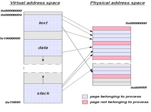
                  Most operating systems use a virtual memory manager (VMM) whose responsibility is to manage the relationship between the virtual organizations of memory as seen by an application with the physical organization of memory from the operating system’s point of view. Virtual memory addresses must be mapped to physical address and vice versa. Write a four to five (4-5) page paper in which you: The memory mapping manager views its local memory as a large cache of the shared virtual memory addresses space for its associated processor (SPECTORA).

How virtual memory addresses get translated into physical addresses step by step.

           Each frame is associated with a register containing

           Residence bit: whether or not the frame is occupied, Occupier: page number of the page occupying frame Protection bits

           Page registers: an example Physical memory size: 16 MB Page size: 4096 bytes Number of frames: 4096

           Space used for page registers (assuming 8 bytes/register): 32

           18 Kbytes

           Percentage overhead introduced by page registers: 0.2%

           Size of virtual memory: irrelevant

           CPU generates virtual addresses, where is the Physical page?

           Hash the virtual address

           Must deal with conflicts

           TLB caches recent translations, so page lookup can take several steps

           Hash the address

           Check the tag of the entry

           Possibly rehash/traverse list of conflicting entries 19

           TLB is limited in size

           Difficult to make large and accessible in a single cycle.

           They consume a lot of power 27% of on-chip for StrongARM .( TARJAN)

         Some physical addresses are decoded to select memory hardware. Physical memory includes ROM as well as RAM. Each block of physical memory has a range of physical addresses. The physical addresses where RAM or ROM can be found depend on the particular computer system (TANG).

          Physical memory does not necessarily occupy sequential addresses. There can be (and often are) gaps, ranges of physical addresses that do not relate to either memory or devices, between ROM addresses and RAM addresses. In most systems, all RAM is given a single sequential span of physical addresses. However, this is not a requirement. Blocks of RAM addresses can also be separated by gaps that are not populated with memory. Since all software uses virtual addresses, software always sees a sequential range of addresses without gaps (IBM).

A Modern operating system translates 32-bit and 64-bit virtual addresses to physical addresses on the same machine.

          The first processor to implement Intel 64 was the multi-socket processor Xeon code named Nocona in June 2004. In contrast, the initial Prescott chips (February 2004) did not enable this feature. Intel subsequently began selling Intel 64-enabled Pentium 4s using the E0 revision of the Prescott core, being sold on the OEM market as the Pentium 4, model F. The E0 revision also adds eXecute Disable (XD) (Intel’s name for the NX bit) to Intel 64, and has been included in the current Xeon code-named Irwindale. Intel’s official launch of Intel 64 (under the name EM64T at that time) in mainstream desktop processors was the N0 Stepping Prescott-2M. All 9xx, 8xx, 6xx, 5×9, 5×6, 5×1, 3×6, and 3×1 series CPUs have Intel 64 enabled, as do the Core 2 CPUs, as will future Intel CPUs for workstations or servers. Intel 64 is also present in the last members of the Celeron D line. Although virtual addresses are 64 bits wide in 64-bit mode, current implementations (and all chips known to be in the planning stages) do not allow the entire virtual address space of 264 bytes (16 EB) to be used. Most operating systems and applications will not need such a large address space for the foreseeable future (for example, Windows implementations for AMD64 are only populating 16 TB, or 44 bits’ worth), so implementing such wide virtual addresses would simply increase the complexity and cost of address translation with no real benefit. AMD therefore decided that, in the first implementations of the architecture, only the least significant 48 bits of a virtual address would actually be used in address translation (page table lookup).  Further, bits 48 through 63 of any virtual address must be copies of bit 47 (in a manner akin to sign extension), or the processor will raise an exception. Addresses complying with this rule are referred to as “canonical form Canonical form addresses run from 0 through 00007FFF’FFFFFFFF, and from FFFF8000’00000000 through FFFFFFFF’FFFFFFFF, for a total of 256 TB of usable virtual address space (AMD).

Relationship diagram between virtual addresses to physical addresses.

vwm


References

AMD Corporation (May 2011).Volume2: System programming, AMD64 Architecture Programmer’s Manual. AMD Corporation. Retrieved December 7, 2012 from http://support.amd.com/us/Embedded_TechDocs/24593.pdf

IBM Corporation, (2007-09-06). IBM WebSphere Application Server 64-bit Performance Demystified. Retrieved from December 7, 2012 ftp://ftp.software.ibm.com/software/webserver/appserv/was/64bitPerf.pdf.

SPECTORA, Z. Performing remote operations efficiently on a local computer network, Common, ACM 25, 4 (Apr. 1982), 260-273

TANG, C. K. (1976). Cache system design in the tightly coupled multiprocessor system, In Proceedings of AFZPS National Computer Conference (New York, N.Y., June 7-10, 1976), AFIPS Press, and Montvale, N.J. 1976, pp. 749-753

TARJAN, R. E., AND VAN LEEUWEN, J. (Apr. 1984), Worst-case analysis of set union algorithms, J.ACM 32, 2 245-281 Retrieved from December 7, 2012. http://techpubs.sgi.com/library/dynaweb_docs/0630/SGI_Developer/books/DevDrvrO2_PG/sgi_html/ch01.html.

********************************************************************************************************************

ECONOMIC TUTORIAL Q/A FOLLOWING ME step by step

********************************************************************************************************************************************************

Eng. – Kingsley

Estimating Demand

Provide an example when it would be appropriate to conduct a time-series or cross sectional data. Evaluate the potential problems that may arise with your example and identify strategies for minimizing the impact of the potential problems.


Cross-sectional data talks about the data collected by observing many subjects at the same point of time, or without regard to differences in time. Analysis of cross-sectional data usually consists of comparing the differences among the subjects. Knowing that these tasks could not be done within existing range or imputation algorithms, so they cannot handle as many variables as needed even in the simpler cross-sectional data for which they were designed, then the need to also develop a new algorithm that substantially expands the range of computationally feasible data types and sizes for which multiple imputation can be used. Cross-sectional, time series, or especially “time-series cross-section” (TSCS) data sets (i.e., those with T units for each of N cross-sectional entities such as countries, where often T < N), as is common in comparative politics and international relations; or for when qualitative knowledge exists about specific missing cell values. The new methods greatly increase the information researchers are able to extract from given amounts of data and are equivalent to having much larger numbers of observations available. Under normal circumstances, researchers can impute once and then analyze the imputed data sets as many times and for as many purposes as they wish (Honaker, 2010).

Discuss the meaning of the regression coefficient of the independent variable(s) and how it could be used to estimate the elasticitys of each of these variables. Discuss how managers use the elasticities measurements to make managerial decisions.


It is important to take into account the uncertainty in the estimation of the regression coefficient. Regression analysis is used when you want to predict a continuous dependent variable from a number of independent variables. If the dependent variable is dichotomous, then logistic regression should be used. (If the split between the two levels of the dependent variable is close to 50-50, then both logistic and linear regression will end up giving you similar results.)in let the “X,” “Y,” “dependent,” “independent” be associated with the magnitude of the regression coefficient ( ) with the change in the dependent variable that results from the unit increase in the independent variable, X.  This magnitude does not tell you how much X changes.   X always increases by one unit to get Y to change by   units. The sign associated with   tells us whether Y increases or decreases by   units when X increases by one unit. (If you begin your interpretation with a unit decrease in X, then remember to reverse the direction indicated by the sign when you describe the change in Y.) . A positive coefficient means X and Y change in the same direction.  If X increases, then Y increases.  If X decreases, then Y decreases.  A negative coefficient means X and Y change in opposite directions.  If X increases, then Y decreases.  If X decreases, then Y increases.


So when you think about it the regression coefficient is not what excel calls them both coefficients, but people should then be concerned and talk about the intercept or constant. Remember that we are talking about changes in X and changes in Y, not levels of either. This is like the idea of a marginal change. It can be stated that the regression line is linear (y = ax + b) the regression coefficient is the constant (a) that represents the rate of change of one variable (y) as a function of changes in the other (x); it is the slope of the regression line (Osgood, 2000).


Reference

Honaker, J. (2010). What to Do about Missing Values in Time-Series Cross-Section Data. American Journal of Political Science, Vol. 54, No. 2, Pp. 561–581 http://gking.harvard.edu/files/gking/files/pr.pdf


Osgood, D.W. (2000). Poisson-Based Regression Analysis of Aggregate Crime Rates.Journal of Quantitative Criminology 16:21-43.


Fundamental Economic Concepts

Pick a recently released good or service. Then, determine the factors that must be evaluated regarding the product’s supply and demand. Analyze how these factors impact the decision to supply the product indicating the significance of each in the decision-making process.

Recently Blackberry released blackberry Q10, after the release of the blackberry Z10.Which now is pointing to weakening sales of the BlackBerry Z10, but strong initial demand for the limited supply of Q10 Smartphone’s, For the first quarter of fiscal 2014 (ending May 2013), his shipment estimates fall to 2.8 million units from 3.3 million previously. Analylist list like Mr. Michael Walkley has warned that Z10 sales could weaken further in the consumer retail as blackberryQ10faces increase competition at the end from Samsung Galaxy S4 and HTC One. As there is no doubt that this strong boost in demand for q10 will lead to decrease in z10 (Ratner, 2013).


Using the same product example above, analyzing how the risk tolerance factors play in supplying the good or service and how this should influence management’s decisions. 

Now you can see timing and managerial decision play its role in this event based on the store checked , the blackberry Q10, has been selling extremely well and has sold out in many stores in march, blackberry report fourth-quarter profit of $98 million this surprised analyst because they had widely expecting a loss (Ratner, 2013). The influence is product modification base on customer demand which increase supply, as well help in the competition market but leads to the decrease in demand of the blackberry Z10. We see this today in all technology it’s better not to change the existing product that to introduce a less demand product the introduction of Blackberry Z10, cause Blackberry to loss as they where uneven with the completion of similar design in the market like the iphone5, Samsung galaxy s4, but the introduction of Blackberry Q10 as a better technology than the Z10 help strengthens their market (Ratner, 2013).


Reference

Ratner, J. (2013).BlackBerry sales forecast cut despite strong demand for Q10.financial post.http://business.financialpost.com/2013/05/06/blackberry-estimates-cut-despite-q10-strength-likely-offsetting-z10-weakness/

See more on daily bases

ECO 550 WK 3 Assignment EC0 550 DICUSSION WK 1 ECO 5500 Week 1 Discussion 2 EC0 550 Week 3 Check Your Understanding Submission ECO 550 Check your understanding Week 2 eco 5500 week 2 DQs Estimating DemandDiscussion 1 Discussion 2. cyberwarfare Discussion 2 Eco 550 Office Building Assignment in research Eco 550 Week 6 Check Your Understanding draft eco 5500 week 2 DQs Estimating Demand ECO 5500 WK2 DQs ECO Assessment 4 ON Research ECO WK 4 Check Your Understanding Eco550 Week 2 Check Your Understanding Monopolies Oligopoly EC0 550 DICUSSION WK 1 EC0 550 Week 3 Check Your Understanding Submission ECO 550 Check your understanding Week 2 ECO 550 WK 3 Assignment ECO 5500 Week 1 Discussion 2


Posted in Uncategorized

Who We Support

phone image

Who We Support

  • Individual with computer, networking, cell phone, laptop cabling and other related issues
  • Comcast
  • PNC Bank
  • Century link
  • Pendum Unlimited
  • DC net
  • Edge Technologies
  • Insight Globe
  • Maryland Department of Transportation AUTHORIT
  • Social Security Administration
  • Center for social change
  • Progress Unlimited
  • Harry corporation tech
  • Rem mentor Network
  • Royal exchange Assurance plc.
  • Noc & co.
  • New day Network
  • Other U.S. federal government customers


Tagged with:
Posted in Uncategorized

Data Backup Onsite/Offsite

cisco routerKingsmich offers IT support for all of your companies’ needs. Do you desire to have in house IT support without the payroll costs, and then you have come to the right place?  We manage your network, so you can manage your business. Our technicians are trained to provide businesses with rapid response support and the highest quality of professionalism. Kingsmich is proud to handle every aspect of your IT needs. From server outages to desktop support, we can solve all of your technology issues at the most affordable prices around

Tagged with: ,
Posted in Uncategorized